![]()
|
|
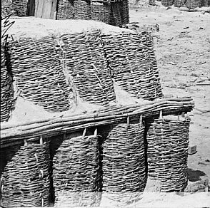
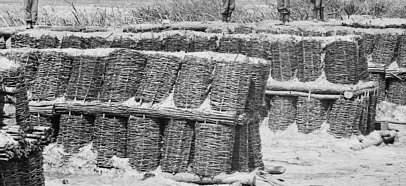
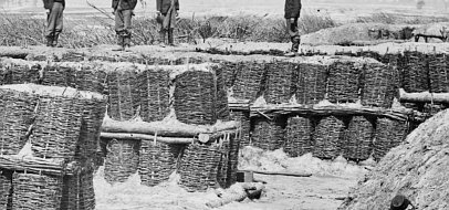
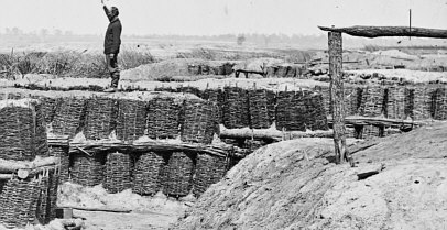
Fort Sedgwick, Federal Siege Lines, Petersburg, Virginia Gabionade Traverses |
|
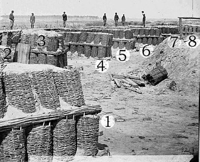
Detailed Characteristics of Traverses In Fort Sedgwick, Federal Line of Countervallation, Siege of Petersburg, Virginia 1864-1865 As Shown In: NA. Petersburg, Virginia. Gabioned parapet of "Fort Hell". (Fort Sedgwick). April 3, 1865. Brady Civil War Photograph Collection (Library of Congress). http://hdl.loc.gov/loc.pnp/cwpb.02614 (Latest Access Check: 27/07/04). [Note: Images of the photograph presented here have been altered for presentation on the internet and have been significantly reduced from the original Library of Congress image used to conduct this examination and are not the actual image or images on which these observations are based.]
This photograph apparently shows a succession of gabionade traverses along
the interior slope of the parapet
Gabionade Traverses
D. H. Mahan described two types of traverses in his work on field fortifications
(Mahan, Treatise, pp. 59-60). The first and larger type was a bomb-proof
traverse intended to intercept direct hostile fire; the second was a smaller
splinter-proof traverse intended to intercept flying fragments of shells.
Gabionade traverses were composed of three basic materials: gabions, fascines,
and earth fill. According to Mahan a bomb-proof
Mahan's description of a splinter-proof traverse is very brief. This type of traverse was to be made with two tiers of gabions. The lower tier consisted of three gabions placed side by side and an upper tier of two gabions. Is is presumed that the details of construction would be the same as a more substantial bomb-proof traverse with four rows of gabions placed on top of the first tier of gabions. (Mahan, Treatise, p.60)
It is important to note that in neither description does Mahan mention placing
the gabions on a fascine foundation nor does he suggest giving the exterior
rows of gabions a slight slope toward the center line of the length of the
gabionade traverse. Mahan's gabionade traverse envisioned gabions placed
in a vertical position
Other sources do mention the necessity for sloping the exterior rows of gabions.
Macaulay indicated that the exterior rows of gabions should be sloped toward
the center of the traverse (Macaulay, Field Fortification, p.70),
but did not give a clear indication of the degree of the slope. Pasley also
noted (Pasley, Batteries, p. 60) that gabions that were not sloped
tended to lose their shape and bulge outward or to one side, an effect that
would have destabilized the structure. He suggested that the slope be produced
by placing sods under the lower outside edge of gabions (the backs of gabions)
rather than simply deforming the gabions into a slope by pushing
Gabions An ordinary gabion was basically a round wicker basket open at the top and bottom. These devices were used to revet all types of slopes from the interior slopes of parapets to, as in the case at hand, traverses. They were generally constructed using the waste material left over after a felled tree had been stripped of its branches and its larger branches had been stripped and sharpened to make pickets or an abatis. When gabions were made according to a specific standard any number of them would have very similar dimensions, that is, all would be about the same height and diameter. This is somewhat important since more or less similar dimensions allow gabions to be taken as a general standard for estimating distances and measures in photographs.
From these various descriptions of the dimensions of gabions it may be safe to conclude that a standard gabion would be about 2 feet 9 inches in height with a diameter of about 2 feet, particularly since the two manuals most likely to be used as procedural guides (Mahan and Duane with Duane relying on Pasley) described the fabrication of gabions with those dimensions. Fascines
A fascine was a bundle of brushwood or long sticks about 1 to 2 inches in
diameter tightly bound together with wire or withes to form a composite
structural material used in the revetment of slopes, as the blindage material,
and, on occasion as fill material. As with gabions, the exact dimensions
of fascines differed from author to author with a general tendency toward
very similar dimensions used for specific purposes. Mahan described two types
of fascines, a regular fascine 10 feet long and 9 inches in diameter and
a larger saucisson that was 20 feet long and 12 inches in diameter (Mahan,
Treatise, p. 39). Pasley described a common fascine that was
Most fascines likely to be used as revetment material were about 9 inches in diameter, but their lengths depended entirely on the length of material required for a particular purpose. This renders the use of fascines alone as a means of estimating lengths and measures in photographs an unreliable tool unless the actual length is know from another source or can be confirmed by some other means more reliable means of measurement.
Observations on Gabionade Traverses As Depicted In This Photograph Parts of 8 gabionade traverses are visible in this photograph. A sufficient portion of 7 of these can be seen to determine their structural characteristics. For convenience each of these traverses has been numbered from 1 to 8 starting from the gabionade traverse nearest the camera on the lower left-hand side of the photograph and proceeding to the farthest traverse that can be clearly viewed in the photograph. Each traverse will be discussed from left to right in numbered succession.
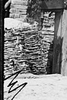
Traverse Number One
This traverse is nearest the camera on the lower left-hand side of the
photograph. Only a small portion near the interior extremity of the traverse
can be seen, but the view is sufficiently close to observe various details
of gabion and fascine construction and the arrangement of these elements
to form the traverse. In this case the traverse was constructed using two
tiers of gabions with an intervening layer of fascines. Gabions of the lower
tier were placed side by side in a vertical position with their outer edges
laid on a raw rounded timber foundation that was pinned in place by one (and
probably more) small stake driven into the ground. The upper
From the loose gabion laying on the rear of the bomb-proof structure these gabions seem to have been fabricated with nine pickets. The webbing seems to have been waled on with three or four rods. Each gabion was constructed using rods of different dimensions. A lack of apparent fill seepage through the lower reaches of the gabions seems to indicate that the webbing was well rammed; the webbing has also been fixed in place by irregularly woven vertical withes that pass through the webbing on one side of a picket and back through the webbing on the other side of a picket. This method, not described in manuals, fixes the webbing in place and ties it to the pickets.
Fascines have been constructed using longer and larger branches of large
trees or, more likely, the small trunks of young trees. Here the rods seem
to be between 1 and 1 1/2 inches and diameter. Wire rather than prepared
withes have been used to bind the fascines together and the ends of the fascines
have been squared or cut to produce an even surface at the end of the
fascines. Traverse Number Two Only one gabion of this traverse can be seen in the photograph. This appears to be an upper tier gabion that has been given a slope toward the center line of the traverse. It has been fabricated from small brushwood and is tied together with withes. Traverse Number Three
This is the first traverse visible from the camera's point of view that provides
good information on the structural form and general characteristics of these
traverses. This traverse was constructed using two tiers of gabions, three
gabions wide on the lower and two wide on the upper tier, with an intervening
layer of 8 fascines. The lower tier of gabions appears to have been placed
on a rectangular foundation of raw timber; the lower tier gabions were also
placed in a vertical position and were not sloped toward the center line
of the traverse. The fascine layer covers the entire width of the lower tier
of gabions. Upper tier gabions have been positioned with
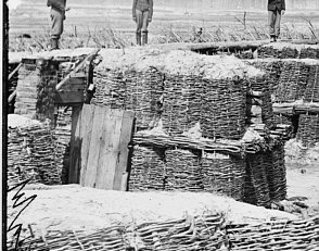
One of the two gun positions (nearest the camera) covered by this traverse has been converted into a shelter with its pole and plank framing attached to the side of the traverse. A pole has been attached to the outer upper edge of the upper tier of gabions that has been used as a support beam for a series of poles laid with one end on the beam and the other, apparently, on the ground inside the gun position. This, along with the irregular plank framing attached to the first lean-to pole and a vertical pole attached to the traverse, marks this as a lean-to structure that probably carried a canvas (tent-half) cover. A door way has also been framed from planks; what appears to be a simple hinged plank and cleat door notched for a wooden latch is resting against the traverse. This must have been a more or less permanent arrangement since a brick and mortar chimney has been constructed at the front of the shelter within the gun position. A somewhat more advantageous view of this gun position shelter is provided by another photograph (NARA 05-0781a) that seems to reveal some sort of shelving attached to the traverse within the shelter. Traverse Number Four
It is notable that the details of the timber foundation of this traverse
can clearly be seen. The foundation appears to be rectangular with two long
raw timbers placed to support the sides of the traverse that run perpendicular
to the supposed direction of the parapet. These have been notched over a
shorter cross piece that supports the interior end of the traverse to lock
them in place and prevent the foundation as whole and the gabions loaded
on it from shifting. In this case the lower tier is three gabions wide at
the end; the gabions
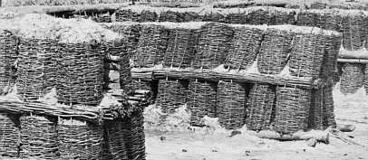
Traverse Number Five
This splinter-proof gabionade traverse has been constructed on the same
principles as the previous two, but with raw timber taking the place of the
layer of fascines intervening between the two tiers of gabions. Like the
previous traverses the lower tier gabions of this one rests on what appears
to be a rectangular timber foundation; but the lower tier, which may originally
been placed in a vertical position, shows greater sign of displacement than
the previous traverses. The end gabion is leaning outward parallel to the
center line of the traverse, the second seems vertical and well positioned,
but the third gabion has taken on a severe slope toward the center line of
the traverse and none of the upper ends of its pickets are visible. Some
of this displacement seems to be due to the use of the solid timber to replace
the layer of fascines. This timber layer appears to be an outline only, after
the fashion of the traverses' timber foundation. Two long pieces running
parallel to the center line of the traverse have been notched over a shorter
cross piece that rests across the
This is also the first traverse in which the tops of all the upper tier gabions are visible from the interior crest of the parapet to the end of the traverse. 13 gabions can be counted in the upper tier, which would make this traverse about 26 feet long. The upper tier gabion closest the parapet does not seem to rest against the parapet since some earth fill can be seen between the interior slope and the end of the gabion, but this may be a perceptional error caused by visible seepage of the earth fill of the traverse between the end gabion and the interior slope. It is also notable that a short vertical timber seems to have been fixed between the end gabions of the two upper tier rows to retain the earth fill. This differs from previous traverses in which material laid horizontally in a direction parallel to the center line of the traverses was used to fill this space. Traverse Number Six
This is the only traverse shown in this photograph that exhibits damage that
can not be credited to construction or settling of the various elements of
the traverse. Like the previous traverses this appears to be a splinter-proof
traverse with two tiers of gabions and an intervening layer of fascines.
The lower tier of gabions rests on a timber foundation while the upper tier,
unlike other traverses, had its end gabions set back from the end of the
lower tier about three-quarters the width of a gabion. Unlike the previous
traverse, only 12 gabions
It is apparent that the outer course of fascine that covers the last 5 gabions of the lower tier has suffered some damage. The end nearest the parapet (left) has some split rods while the other end (right) seems to have become unbound and is separating. The parapet end of this fascine does not join smoothly with the next outer course fascine, but seems to have been displaced, as have the five gabions of the lower tier that it covers. This displacement had not yet reached a point sufficient to destabilize the upper tier of gabions, which seem to retain a consistent slope and height throughout the length of the traverse. Traverses Numbers Seven and Eight
|
|
|
|
|
August, 2004 |


 forming the right face of the right redan of Fort
Sedgwick. This section of the fort was arranged in the form of a battery
with an artillery armament mounted to fire through embrasures (Hopkins Plan,
Michler Map). In this case the traverses separated embrasured positions for
one or two guns. Traverses in batteries served to both protect the gun and
its crew from hostile fire (by defilading the gun position and protecting
it from shell burst within the battery) and limit the destructive effects
of an explosion of powder or bursting of a gun to a single gun position.
forming the right face of the right redan of Fort
Sedgwick. This section of the fort was arranged in the form of a battery
with an artillery armament mounted to fire through embrasures (Hopkins Plan,
Michler Map). In this case the traverses separated embrasured positions for
one or two guns. Traverses in batteries served to both protect the gun and
its crew from hostile fire (by defilading the gun position and protecting
it from shell burst within the battery) and limit the destructive effects
of an explosion of powder or bursting of a gun to a single gun position.
 traverse was constructed with two tiers of gabions
separated by a layer of fascines. The lower tier of gabions was laid out
in a rectangular pattern to enclose a space about 12 feet by 24 feet. A second
row of gabions was placed inside the first and both rows of gabions and the
center void were filled with earth. A layer of four fascines was then laid
side by side along the tops of both rows of gabions. A second tier of gabions
was then placed on top and slightly away from the edge of the outer row of
the first tier of gabions. The thickness of this type of gabionade traverse
was considered capable of intercepting hostile small arms and direct artillery
fire and would be used as a defilade traverse when the interior of a field
work could be reached from commanding ground or by ricochet fire along the
face or flank of a field work. (Mahan, Treatise, p. 60)
traverse was constructed with two tiers of gabions
separated by a layer of fascines. The lower tier of gabions was laid out
in a rectangular pattern to enclose a space about 12 feet by 24 feet. A second
row of gabions was placed inside the first and both rows of gabions and the
center void were filled with earth. A layer of four fascines was then laid
side by side along the tops of both rows of gabions. A second tier of gabions
was then placed on top and slightly away from the edge of the outer row of
the first tier of gabions. The thickness of this type of gabionade traverse
was considered capable of intercepting hostile small arms and direct artillery
fire and would be used as a defilade traverse when the interior of a field
work could be reached from commanding ground or by ricochet fire along the
face or flank of a field work. (Mahan, Treatise, p. 60)
 without any slope. Nor is there any mention of connecting
the upper or lower tiers of gabions with wire or withes to bond the separate
elements into a unified structure.
without any slope. Nor is there any mention of connecting
the upper or lower tiers of gabions with wire or withes to bond the separate
elements into a unified structure.
 the upper half inward toward the center of the traverse.
A. F. Lendy provided an illustration of a splinter-proof traverse in which
a slope is produced by placing the gabions in a trench with sloped sides
(Lendy, Treatise, p. 231). The chapter on construction of batteries
in Duane's Manual for Engineer Troops provides details on constructing
battery traverses using gabions in which the outer row of gabions of both
the first and second tier are sloped by using one row fascines and placing
the outer edge of gabions on the fascine. These instructions also suggest
that gabions be tied together using wire or rope. (Duane, Manual,
pp. 249-251).
the upper half inward toward the center of the traverse.
A. F. Lendy provided an illustration of a splinter-proof traverse in which
a slope is produced by placing the gabions in a trench with sloped sides
(Lendy, Treatise, p. 231). The chapter on construction of batteries
in Duane's Manual for Engineer Troops provides details on constructing
battery traverses using gabions in which the outer row of gabions of both
the first and second tier are sloped by using one row fascines and placing
the outer edge of gabions on the fascine. These instructions also suggest
that gabions be tied together using wire or rope. (Duane, Manual,
pp. 249-251).
 According to Mahan's Treatise an ordinary gabion
when finished would be about 2 feet 9 inches tall with a diameter of 2 feet
(Mahan, Treatise, p. 39). Other authors give similar dimensions, with
some variations according to the application of the gabion. Joshua Jebb
(Siege Duties, pp. 73-75) gives a height of 3 feet and diameter of
2 feet for a light sap gabion. Lendy (Elements, p. 81) gives gabions
a height of 3 feet and diameter of 2 to 3 feet and in another source (Lendy,
Treatise, p. 225) gives the dimensions of a sap gabion as 2 feet 9
inches long and 2 feet in diameter. Macauley indicates that a parapet revetment
gabion should be 3 feet long and 3 feet in diameter while a common gabion
as used in sap should be 2 feet 9 inches long and 2 feet in diameter. Pasley
remarks that gabions made at the engineer establishment at Chatham were 2
feet 9 inches tall and 2 feet in diameter, though other sizes had been tired
and rejected as being no more effective.
According to Mahan's Treatise an ordinary gabion
when finished would be about 2 feet 9 inches tall with a diameter of 2 feet
(Mahan, Treatise, p. 39). Other authors give similar dimensions, with
some variations according to the application of the gabion. Joshua Jebb
(Siege Duties, pp. 73-75) gives a height of 3 feet and diameter of
2 feet for a light sap gabion. Lendy (Elements, p. 81) gives gabions
a height of 3 feet and diameter of 2 to 3 feet and in another source (Lendy,
Treatise, p. 225) gives the dimensions of a sap gabion as 2 feet 9
inches long and 2 feet in diameter. Macauley indicates that a parapet revetment
gabion should be 3 feet long and 3 feet in diameter while a common gabion
as used in sap should be 2 feet 9 inches long and 2 feet in diameter. Pasley
remarks that gabions made at the engineer establishment at Chatham were 2
feet 9 inches tall and 2 feet in diameter, though other sizes had been tired
and rejected as being no more effective.
 The only difference between battery-gabions and
trench-gabions was the dimensions of the material used to fabricate them;
battery gabions requiring somewhat wider (and therefore more durable) rods
(Pasley, Siege Operations, p. 13). French sources generally give
dimensions in metric measures: Laisne (Aide-Memoire, p. 503) says
that an ordinary gabion should have a height of .8 meters and diameter of
.65 meters with pickets 1 meter long. The Aide-Memoire a l'Usage des Officiers
d'Artillerie (1836) gives two different sizes of gabions: a battery gabion
1 meter long and .56 meter in diameter and a gabion roller (or sap roller,
which was not used for revetments) 2.3 meters long and 1.3 meters in diameter.
(Officiers d'Artillerie, p. 249).
The only difference between battery-gabions and
trench-gabions was the dimensions of the material used to fabricate them;
battery gabions requiring somewhat wider (and therefore more durable) rods
(Pasley, Siege Operations, p. 13). French sources generally give
dimensions in metric measures: Laisne (Aide-Memoire, p. 503) says
that an ordinary gabion should have a height of .8 meters and diameter of
.65 meters with pickets 1 meter long. The Aide-Memoire a l'Usage des Officiers
d'Artillerie (1836) gives two different sizes of gabions: a battery gabion
1 meter long and .56 meter in diameter and a gabion roller (or sap roller,
which was not used for revetments) 2.3 meters long and 1.3 meters in diameter.
(Officiers d'Artillerie, p. 249).
 18 feet long and 9 inches in diameter. This long
fascine could be cut to any length needed. Trench fascines were produced
by cutting a common fascine into three equal 6 foot long fascines or cut
into two 9 feet long fascines to cover blinded galleries (Pasley, Siege
Operations, p.5). Macaulay and Lendy both described fascines made using
small brushwood that were 6 feet long with a diameter of 7 inches. Both also
indicated that the size of a fascine depended on the dimensions of the material
used to make them (Macaulay, Field Fortification, pp. 58-60 and Lendy,
Treatise, p. 148). Francais described a fascine 3 meters long and
.22 to .24 meters in diameter (Francais, Precis, p. 167). Laisne described
a number of different fascines made in different lengths for distinct purposes.
His revetment fascine was 2 meters long and .22 meters in diameter with squared
ends. A stuffed fascine was 2.3 meters long and .22 in diameter and a crowning
fascines had the same dimension as a revetment fascine without squared ends
(Laisne, Aide-Memoire, pp 501-503).
18 feet long and 9 inches in diameter. This long
fascine could be cut to any length needed. Trench fascines were produced
by cutting a common fascine into three equal 6 foot long fascines or cut
into two 9 feet long fascines to cover blinded galleries (Pasley, Siege
Operations, p.5). Macaulay and Lendy both described fascines made using
small brushwood that were 6 feet long with a diameter of 7 inches. Both also
indicated that the size of a fascine depended on the dimensions of the material
used to make them (Macaulay, Field Fortification, pp. 58-60 and Lendy,
Treatise, p. 148). Francais described a fascine 3 meters long and
.22 to .24 meters in diameter (Francais, Precis, p. 167). Laisne described
a number of different fascines made in different lengths for distinct purposes.
His revetment fascine was 2 meters long and .22 meters in diameter with squared
ends. A stuffed fascine was 2.3 meters long and .22 in diameter and a crowning
fascines had the same dimension as a revetment fascine without squared ends
(Laisne, Aide-Memoire, pp 501-503).
 tier of gabions has been positioned at an angle
with the protruding pickets placed inside the outer row of fascines to create
a more or less consistent slope along the upper tier of gabions. The earth
fill material has been heaped up above the level of the top of the upper
tier of gabions and has steeped through the small intervals between both
upper and lower tier gabions.
tier of gabions has been positioned at an angle
with the protruding pickets placed inside the outer row of fascines to create
a more or less consistent slope along the upper tier of gabions. The earth
fill material has been heaped up above the level of the top of the upper
tier of gabions and has steeped through the small intervals between both
upper and lower tier gabions.
 their pickets roughly even with the diameter of the
outer course of fascines to give the upper tier gabions a very slight slope
that does not deform the gabions' cylindrical shape. A fascine topped with
several quartered timbers of diminishing width has been placed between the
two rows of upper tier gabions. These general characteristics mark this as
a splinter-proof traverse designed to limit damage within the battery rather
than bomb-proof defilade traverses that would be capable of intercepting
hostile artillery fire.
their pickets roughly even with the diameter of the
outer course of fascines to give the upper tier gabions a very slight slope
that does not deform the gabions' cylindrical shape. A fascine topped with
several quartered timbers of diminishing width has been placed between the
two rows of upper tier gabions. These general characteristics mark this as
a splinter-proof traverse designed to limit damage within the battery rather
than bomb-proof defilade traverses that would be capable of intercepting
hostile artillery fire.
 appear to have been along the top of the timber
foundation at a slight angle toward the center line of the traverse. The
intervening layer of fascines fully covered the lower tier gabions. Upper
tier gabions were laid with the outside pickets protruding over the outside
course of fascines and have been given a much sharper angle than the upper
tier gabions of traverse number three. Here too a single fascine has been
positioned along the center line of the traverse on top of the fascine layer,
but unlike traverse number three, the fascine has not been topped with quartered
timber. This alone allows the upper tier gabions to take a somewhat greater
slope than those of traverse number three. The end gabion of the upper tier
farthest from the camera has been somewhat severely displaced and seems to
be leaning toward and over the end of the lower tier gabion. This might have
been due to an original misplacement of the gabion during construction, to
settling of the fill and gabion, to the weight of the earth fill, or to any
combination of these causes. That it stands in this position seems to indicate
that the gabion has been fairly well bonded to the body of the traverse either
through the action of the earth fill seeping though the rods on the interior
side of the gabion or due to some other means of bonding such as rope or
wires ties connecting one gabion to one or more of the other gabions.
appear to have been along the top of the timber
foundation at a slight angle toward the center line of the traverse. The
intervening layer of fascines fully covered the lower tier gabions. Upper
tier gabions were laid with the outside pickets protruding over the outside
course of fascines and have been given a much sharper angle than the upper
tier gabions of traverse number three. Here too a single fascine has been
positioned along the center line of the traverse on top of the fascine layer,
but unlike traverse number three, the fascine has not been topped with quartered
timber. This alone allows the upper tier gabions to take a somewhat greater
slope than those of traverse number three. The end gabion of the upper tier
farthest from the camera has been somewhat severely displaced and seems to
be leaning toward and over the end of the lower tier gabion. This might have
been due to an original misplacement of the gabion during construction, to
settling of the fill and gabion, to the weight of the earth fill, or to any
combination of these causes. That it stands in this position seems to indicate
that the gabion has been fairly well bonded to the body of the traverse either
through the action of the earth fill seeping though the rods on the interior
side of the gabion or due to some other means of bonding such as rope or
wires ties connecting one gabion to one or more of the other gabions.
 ends of the lower tier of gabions. The leaning outside
gabion of the lower tier carries the weight of this timber frame and the
upper tier of gabions (along with the earth fill) directly on top of one
picket. It appears that the weight of the mass has leveraged this gabion
out of place and is slowly ripping the gabion away from the body of the traverse.
ends of the lower tier of gabions. The leaning outside
gabion of the lower tier carries the weight of this timber frame and the
upper tier of gabions (along with the earth fill) directly on top of one
picket. It appears that the weight of the mass has leveraged this gabion
out of place and is slowly ripping the gabion away from the body of the traverse.
 can be counted in the upper tier. No hard fill material
was placed on the fascine layer to help seal the space between the lower
halves of the upper gabions; this has allowed the earth fill to seep out
toward the end between the upper rows. While the gabion nearest the interior
slope does not seem to make contact with the slope, earth fill seems to complete
contact between the traverse and the parapet.
can be counted in the upper tier. No hard fill material
was placed on the fascine layer to help seal the space between the lower
halves of the upper gabions; this has allowed the earth fill to seep out
toward the end between the upper rows. While the gabion nearest the interior
slope does not seem to make contact with the slope, earth fill seems to complete
contact between the traverse and the parapet.
 These two traverses can be seen with sufficient
clarity to make any very useful observations other than they seem to follow
the pattern set by the preceding traverses. Both were constructed with two
tiers of gabions; Number 7 seems to have a timber frame layer between the
tiers while Number Eight has an intervening layer of fascines. Although this
may be a perceptional error, Number 7 seems to have three gabions at the
end of its upper tier. This would make it bomb-proof rather than splinter-proof
and capable of resisting direct hostile artillery fire.
These two traverses can be seen with sufficient
clarity to make any very useful observations other than they seem to follow
the pattern set by the preceding traverses. Both were constructed with two
tiers of gabions; Number 7 seems to have a timber frame layer between the
tiers while Number Eight has an intervening layer of fascines. Although this
may be a perceptional error, Number 7 seems to have three gabions at the
end of its upper tier. This would make it bomb-proof rather than splinter-proof
and capable of resisting direct hostile artillery fire.
