![]()
|
|
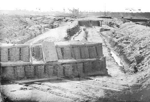
Embrasure and Connecting Parapet, Fort Sedgwick to Battery XXI, Federal Line of Countervallation, Siege of Petersburg, Virginia 1864-1865 |
|
Embrasure and Connecting Parapet, Fort Sedgwick to Battery XXI, Federal Line of Countervallation, Siege of Petersburg, Virginia, 1864-1865 As Shown In NA. Petersburg, Virginia. View on the Petersburg lines from the right of Fort Sedgwick. Brady Civil War Photograph Collection (Library of Congress). http://hdl.loc.gov/loc.pnp/cwpb.03715 (Last Access Check: 20/07/04). [Note: Images of the photograph presented here have been altered for presentation on the internet and have been significantly reduced from the original Library of Congress image used to conduct this examination and are not the actual image or images on which these observations are based.]
This photograph focuses on the connecting parapet that joined the extreme right of Fort Sedgwick's right redan battery (closest to the camera) with the extreme left of the redan shaped Battery XXI. The significant features that will be discussed here include: 1) the interior slope of the parapet and embrasure closest to the camera; 2) the connecting parapet and interior slope revetment; and 3) the corduroy covered way immediately in rear of the connecting parapet.
Interior Slope, Gun Platform, and Embrasure (Fort Sedgwick)
Fort Sedgwick's right redan was strictly arranged as a battery
with a parapet height of 80 to 85 inches above the level of gun platforms
without a banquette for musket fire. Its artillery armament was mounted to
fire through embrasures pierced through the body of the parapet. The interior
slope, as shown in this photograph, was revetted with two tiers of gabions.
Round raw timber was used for the footing, middle tying layer, and crown
of the revetment in place of fascines. In this case the lower tier of gabions
has a fairly consistent vertical angle with their pickets placed inside of
rather than resting directly on the timber footing except that portion in
Raw timber was used in place of fascines to form the intervening
anchoring layer between the lower and upper tier of gabions. Interestingly,
these timbers, which appear to have a fairly uniform diameter, where not
merely laid on top of the lower tier of gabions as fascines would have been.
Rather, the timbers have been anchored to the body of the parapet by being
laid on and notched onto round timber cross anchor ties that probably pass
over the tops of the lower tier gabions and extended into the body of the
parapet in front of the
Upper tier gabions have been laid on top the lower tier gabions with their protruding lower pickets positioned inside the anchoring layer of timber. This indicates that the layer of anchoring timbers simply holds the lower reaches of the upper tier gabions in place and prevents them from sliding outside rather than acting as a true bonding device to create a structurally unified revetment. This role was performed solely be the protruding gabion pickets when the upper tier was placed on top of the lower tier gabions. Upper tier gabions are crowned by another course of round raw timber which has been laid inside the outer gabion pickets.Like the anchoring course between the gabion tiers, timbers of the crowning course were probably joined together in the same fashion as the anchoring course using rabbet notches. Timbers were held in place by quartered timber anchoring ties that were notched on top of the crowning timbers at one at and buried in the body of the parapet at the other. These served as anchors in much the same fashion as pickets driven through a course of fascines. Since the anchoring ties were on top of the crowning timbers it was probably hoped that this arrangement would hold the timbers in place when struck by solid shot.
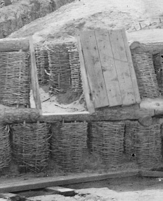
An embrasure that is protected by a hinged shutter mantlet has
been cut through this parapet. This embrasure is somewhat wider than the
average diameter of gabions of the surrounding revetment; if an average diameter
That this embrasure was provided a shutter mantlet indicates that
there was some perceived danger from hostile small arms fire. It is notable
that Fort Sedgwick was well within small arms range of the opposing Confederate
picket line and main line of field works. In this case the embrasure has
been framed with two
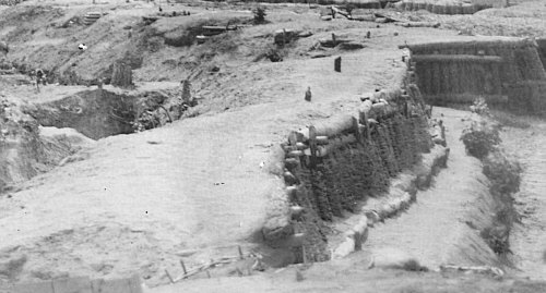
Connecting Parapet
A relatively short section of parapet prepared for a musket armament
connected the right of Fort Sedgwick with the left of the redan shaped Battery
XXI and acted as a curtain covering a retired section of the continuous line
of parapet. This parapet is visible in the middle distance of the photograph.
This parapet seems, for the most part, to have had a rather normal sort of
profile that included a distinct banquette slope, banquette, and a well revetted
interior slope. The superior slope seems to meld almost seamlessly into the
exterior slope which drops off into the ditch in front of the parapet. There
is no discernible
The most notable feature of this parapet is the revetment of the interior slope. Gabions were the primary revetment material. These have been fixed along the foot of the interior crest by a course of raw timber laid against the gabions and pinned in place by short pickets. The gap between the footing timbers and gabions has been filled with earth to form a narrow step. Height of the parapet has been increased by crowning the gabions with two courses of timber. These timbers have been fixed in place with notched cross anchoring timbers that extend into the body of the parapet along with upright staves driven into the earth fill of some of the gabions. This last measure was probably intended as a safety measure to prevent the crowning timbers being knocked onto troops manning the parapet in the event that hostile artillery fire struck the parapet near the interior crest.
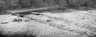
Defilade Excavation, Covered Way
|
|
|
|
|
August, 2004 |


 front of the gun platform. Most of the deck planking
and all save one of the sleepers of the platform has been removed except
those planks that were underneath the timber footing of the revetment. This
would seem to indicate that the platform was already in place when this revetment
was constructed. Although this may be a perceptional error, the platform
deck planks that remain do not seem to be positioned parallel to the foot
of the interior slope of the parapet, indicating that this may have been
an oblique rather than direct embrasure.
front of the gun platform. Most of the deck planking
and all save one of the sleepers of the platform has been removed except
those planks that were underneath the timber footing of the revetment. This
would seem to indicate that the platform was already in place when this revetment
was constructed. Although this may be a perceptional error, the platform
deck planks that remain do not seem to be positioned parallel to the foot
of the interior slope of the parapet, indicating that this may have been
an oblique rather than direct embrasure.
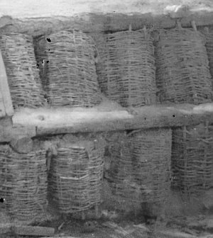 revetment. In this photograph two of these anchoring
ties are visible, one near the extremity of the revetment and one just below
the point where two anchoring layer timbers have been joined by a notched
overlapping rabbet joint. This type of arrangement would not have been necessary
with a fascine anchoring layer since the interaction of the protruding pickets
of the upper and lower gabions with the voids between fascine rods would
have held the fascines in place.
revetment. In this photograph two of these anchoring
ties are visible, one near the extremity of the revetment and one just below
the point where two anchoring layer timbers have been joined by a notched
overlapping rabbet joint. This type of arrangement would not have been necessary
with a fascine anchoring layer since the interaction of the protruding pickets
of the upper and lower gabions with the voids between fascine rods would
have held the fascines in place.
 of 24 inches is assumed, then this embrasure is
between 34 and 36 inches wide or nearly three feet wide. This is much wider
than most manuals would prescribe for the mouth of an embrasure. Mahan allowed
the mouth of an embrasure to be between 18 inches and 2 feet wide
(Treatise, p. 54). In his work on siege batteries Pasley described
embrasures for elevated batteries as being 2 feet wide (Pasley,
Batteries, p.9). Since the width of this embrasure is wider than a
single gabion it may be presumed that the embrasure pre-dated the revetment
and that the gabion revetment was constructed around the mouth of the embrasure
rather than the embrasure cut through the parapet after the revetment had
been established. A wider embrasure mouth would allow a gun firing through
to traverse through a wider arc and increase the gun's field of fire. Since
this gun is in a re-entrant angle it may be assumed that it was primarily
intended for flank defense of the collateral salient (visible in the background)
and was widened so that it could strike targets at a greater than normal
distance in front of the re-entrant and collateral salient angles.
of 24 inches is assumed, then this embrasure is
between 34 and 36 inches wide or nearly three feet wide. This is much wider
than most manuals would prescribe for the mouth of an embrasure. Mahan allowed
the mouth of an embrasure to be between 18 inches and 2 feet wide
(Treatise, p. 54). In his work on siege batteries Pasley described
embrasures for elevated batteries as being 2 feet wide (Pasley,
Batteries, p.9). Since the width of this embrasure is wider than a
single gabion it may be presumed that the embrasure pre-dated the revetment
and that the gabion revetment was constructed around the mouth of the embrasure
rather than the embrasure cut through the parapet after the revetment had
been established. A wider embrasure mouth would allow a gun firing through
to traverse through a wider arc and increase the gun's field of fire. Since
this gun is in a re-entrant angle it may be assumed that it was primarily
intended for flank defense of the collateral salient (visible in the background)
and was widened so that it could strike targets at a greater than normal
distance in front of the re-entrant and collateral salient angles.
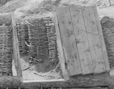 stiles. The lower end of the stiles have been attached
to the edges of a cut out in the anchoring timber below the embrasure mouth.
The upper ends have been attached to the ends of the crowning timbers, which
were cut through to open the embrasure along the interior crest of the parapet.
This shutter was constructed in a rather ad hoc fashion using 3 full and
one ripped plank. Three of these planks appear to be about 8 inches wide
and 46 to 48 inches long, the striking plank appears to be about 2 or 3 inches
wide. Although the back of the shutter is not visible it seems likely that
the shutter planks were fixed in place by two cleats or battens. A dark area
on the hinge stile (on the right) may be the location of a hinge, but the
type of hinge used to fix the shutter to the stile can not be determined
from the photograph.
stiles. The lower end of the stiles have been attached
to the edges of a cut out in the anchoring timber below the embrasure mouth.
The upper ends have been attached to the ends of the crowning timbers, which
were cut through to open the embrasure along the interior crest of the parapet.
This shutter was constructed in a rather ad hoc fashion using 3 full and
one ripped plank. Three of these planks appear to be about 8 inches wide
and 46 to 48 inches long, the striking plank appears to be about 2 or 3 inches
wide. Although the back of the shutter is not visible it seems likely that
the shutter planks were fixed in place by two cleats or battens. A dark area
on the hinge stile (on the right) may be the location of a hinge, but the
type of hinge used to fix the shutter to the stile can not be determined
from the photograph.
 berm between the exterior slope and ditch.
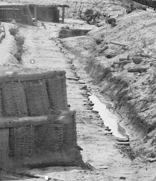 Ground immediately in rear of the parapet's
banquette was defiladed by excavation. This created a short covered way several
yards wide that allowed troops to pass behind the parapet without being seen
by the enemy. But it also seems to have created a drainage problem. This
area was enclosed by the parapet on one side and the covering mass of a series
of bomb-proof structures on the other. This passage way slopes downward from
the left of Battery XXI and rises again where it joins the gun position covered
by Fort Sedgwick's parapet. In other words, the defilade excavation created
a basin that naturally collected run-off from the surrounding sloped surfaces
and converted the covered way into a permanent mud-pit. This problem has
been dealt with by corduroying the covered way with timber and excavating
a small drainage trench along the base of the bomb-proof covering mass to
catch the run-off and carry it to the lowest section of the trench, which
was apparently allowed to act as a cess-pool where water would stand until
absorbed into the soil. Since there does not seem to be any outlet or drain
to direct water down the hill around the bomb-proof, this area would probably
be subject to flooding during particularly heavy or persistent rains.
Ground immediately in rear of the parapet's
banquette was defiladed by excavation. This created a short covered way several
yards wide that allowed troops to pass behind the parapet without being seen
by the enemy. But it also seems to have created a drainage problem. This
area was enclosed by the parapet on one side and the covering mass of a series
of bomb-proof structures on the other. This passage way slopes downward from
the left of Battery XXI and rises again where it joins the gun position covered
by Fort Sedgwick's parapet. In other words, the defilade excavation created
a basin that naturally collected run-off from the surrounding sloped surfaces
and converted the covered way into a permanent mud-pit. This problem has
been dealt with by corduroying the covered way with timber and excavating
a small drainage trench along the base of the bomb-proof covering mass to
catch the run-off and carry it to the lowest section of the trench, which
was apparently allowed to act as a cess-pool where water would stand until
absorbed into the soil. Since there does not seem to be any outlet or drain
to direct water down the hill around the bomb-proof, this area would probably
be subject to flooding during particularly heavy or persistent rains.
