Manassas Junction, Virginia. Confederate Fortifications, East Front,
Interior Line of Open Detached Field Works.
As Shown In:
Barnard, George N. Manassas, Va. Confederate Fortifications, with Federal
Soldiers. March, 1862. Brady Civil War Photograph Collection (Library
of Congress). http://hdl.loc.gov/loc.pnp/cwpb.03910 (Last Access Check:
04/08/02). Noted as 03910u.
Barnard, George N., Manassas, Virginia. Fortifications. March,1862.
Brady Civil War Photograph Collection (Library of Congress).
http://hdl.loc.gov/loc.pnp/cwpb.00102 (Last Access Check: 07/08/04). Noted
as 00102u.
Barnard, George N., Manassas, Va. Confederate Fortifications, with Federal
Soldiers. March, 1862. Brady Civil War Photograph Collection (Library
of Congress). http://hdl.loc.gov/loc.pnp/cwpb.04332 (Last Access Check:
07/08/04). Noted as 04332u.
O'Sullivan, Timothy H., Manassas, Virginia. Eastern Range of Confederate
Defenses. July, 1862. Brady Civil War Photograph Collection (Library
of Congress). http://hdl.loc.gov/loc.pnp/cwpb.01084 (Last Access Check:
07/08/04). Noted as 01084u.
[Please Note: Images presented here are for illustration purposes
only. These are not the original images of photographs discussed in the text
and are not the images that these observations are based on. Images are
referenced by the Library of Congress filenames of the original images of
the photographs downloaded from the Library of Congress web site.]
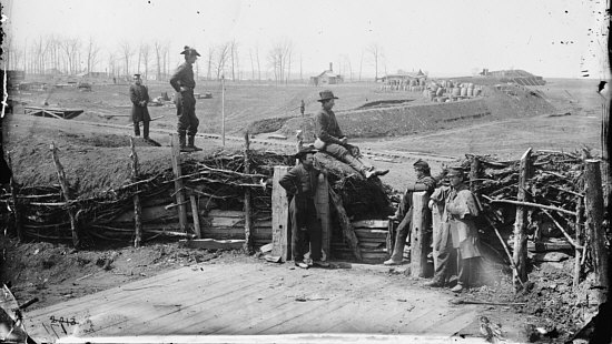
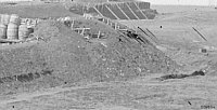
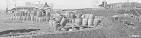
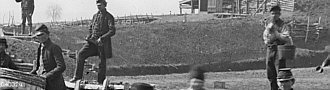
This photograph shows four field works constructed by Confederate
forces to defend Manassas Junction, Virginia according to a plan developed
by engineer Thomas H. Williamson in the spring of 1861. Williamson's plan
for the defense (which may have been later modified by P.G.T. Beauregard
and his staff) of the vital rail junction and supply depot envisioned an
interior ring of open detached field works that covered all avenues of
 approach that an enemy might take to reach the junction. An
advanced line of enclosed detached field works guarded the distant approaches
to the supply depot from the direction of Centreville and Bull Run Creek.
These four works are shown in the detail from the Whiting Map of Manassas
Junction to the right. They extended from just south of the Orange and
Alexandria Railroad in a roughly northwest direction for a distance of about
360 yards. approach that an enemy might take to reach the junction. An
advanced line of enclosed detached field works guarded the distant approaches
to the supply depot from the direction of Centreville and Bull Run Creek.
These four works are shown in the detail from the Whiting Map of Manassas
Junction to the right. They extended from just south of the Orange and
Alexandria Railroad in a roughly northwest direction for a distance of about
360 yards.
Several features can be viewed in sufficient detail in this (and
other photographs which will be introduced as necessary) to allow some effective
comment on the construction of these field works. First, the interior details
of the battery south of the railroad from which this photograph was taken
(marked A on the map); second the profile and exterior details of the first
redan on the north side of the railroad along with its odd barrel traverses
(marked as B on the map); and third, both interior revetment and exterior
details of the large redan in the distant background that covered the
salient angle joining the east and north fronts of the interior line of works
(marked D on the map). The smaller battery (marked C on the map) between
the first and second works north of the railroad can not be seen with sufficient
clarity to make any but the most cursory comments on its trace or structural
substance.
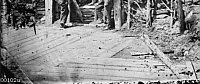
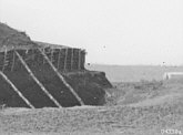
I. Battery Interior (A)
 This battery was positioned on the left face
and salient of an irregular redan immediately south of the Orange and Alexandria
Railroad where its embrasured naval ordnance could fire both across the front
of collateral works to the north and eastward along the line of the railroad
tracks. Both the basic materials used to construct this battery and the
arrangement of the revetment of the interior slope can be seen in the foreground.
This is a split revetment that combined the post and timber revetment method
for sustaining the lower section of the interior slope with a rough hurdle
work to sustain the upper section of the slope. Posts were fixed in the ground
at somewhat irregular intervals averaging about 3 feet from post to post
along the foot of the interior slope. The lower section of the revetment
was constructed This battery was positioned on the left face
and salient of an irregular redan immediately south of the Orange and Alexandria
Railroad where its embrasured naval ordnance could fire both across the front
of collateral works to the north and eastward along the line of the railroad
tracks. Both the basic materials used to construct this battery and the
arrangement of the revetment of the interior slope can be seen in the foreground.
This is a split revetment that combined the post and timber revetment method
for sustaining the lower section of the interior slope with a rough hurdle
work to sustain the upper section of the slope. Posts were fixed in the ground
at somewhat irregular intervals averaging about 3 feet from post to post
along the foot of the interior slope. The lower section of the revetment
was constructed
 by laying irregular split and cut timber between these posts
and packing the earth of the parapet against them to bond the revetment.
When this revetment reached a height of about 2 and one-half feet rough hurdle
work consisting of the larger unstripped branches of cedar trees were run
in and out between the posts. As the soil was thrown onto the parapet small
leafy branches were laid on the rising parapet to both decrease the amount
of soil required to construct the parapet and better bond the somewhat rocky
soil into a solid mass. This also tended to increase the parapet's resistance
to the erosive effects of wind and rain. by laying irregular split and cut timber between these posts
and packing the earth of the parapet against them to bond the revetment.
When this revetment reached a height of about 2 and one-half feet rough hurdle
work consisting of the larger unstripped branches of cedar trees were run
in and out between the posts. As the soil was thrown onto the parapet small
leafy branches were laid on the rising parapet to both decrease the amount
of soil required to construct the parapet and better bond the somewhat rocky
soil into a solid mass. This also tended to increase the parapet's resistance
to the erosive effects of wind and rain.
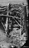 Much of the revetment shown in this photograph
(which was made about a year after these works had been completed) had suffered
quite a bit of deterioration and was in a generally dilapidated condition.
To the right of the embrasure most of the small branches holding the interior
slope in place have rotted away or suffered other debilitating damage and
the soil is beginning to fall and form a mound at the foot of the interior
slope. Still, most of the revetment posts seem to be well fixed and many
of the larger branches of the hurdle work Much of the revetment shown in this photograph
(which was made about a year after these works had been completed) had suffered
quite a bit of deterioration and was in a generally dilapidated condition.
To the right of the embrasure most of the small branches holding the interior
slope in place have rotted away or suffered other debilitating damage and
the soil is beginning to fall and form a mound at the foot of the interior
slope. Still, most of the revetment posts seem to be well fixed and many
of the larger branches of the hurdle work
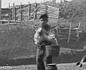
 continue to sustain the soil. Another photograph
(00102u) shows that the section of the revetment immediately to the right
of the revetment shown in this photograph had completely rotted away and
the interior slope had fallen onto the foot of the interior slope and gun
platform. To the left of the embrasure the small branches of the hurdle work
were giving way when the photograph was made; weight of the parapet's rocky
soil was bending the surviving branches and beginning to rotate one of the
posts backward and to one side. continue to sustain the soil. Another photograph
(00102u) shows that the section of the revetment immediately to the right
of the revetment shown in this photograph had completely rotted away and
the interior slope had fallen onto the foot of the interior slope and gun
platform. To the left of the embrasure the small branches of the hurdle work
were giving way when the photograph was made; weight of the parapet's rocky
soil was bending the surviving branches and beginning to rotate one of the
posts backward and to one side.
Most of the batteries in the Manassas defenses were designed
specifically for handling heavy naval ordnance mounted on ship's trucks rather
than standard land service carriages. In this case the embrasure had a
 genouilliere about 2 and one-half feet above
the foot of the interior slope that was sustained by a vertical post and
timber revetment. A short vertical post at the center of the embrasure
genouilliere under the embrasure neck marks an angle in the work where the
line of the interior crest changes direction. This would have allowed a gun
mounted at this embrasure a slightly wider field of fire than normal, but
also required that a short horizontal huerter be placed on the terre-plein
to prevent the gun truck from being run to far into the embrasure. The four
horizontal posts, two on either side of the embrasure, that are not part
of the revetment were tackle posts. Dark circles in these posts mark the
holes where eye-bolts were once attached. Breeching tackle used to maneuver
a gun mounted on a ship's truck and catch the gun as it recoiled when fired
was run through the eye-bolts on these tackle posts and attached to the truck.
This confirms reports that naval ordnance captured at the Norfolk Navy Yard
actually was mounted in the Manassas defenses. genouilliere about 2 and one-half feet above
the foot of the interior slope that was sustained by a vertical post and
timber revetment. A short vertical post at the center of the embrasure
genouilliere under the embrasure neck marks an angle in the work where the
line of the interior crest changes direction. This would have allowed a gun
mounted at this embrasure a slightly wider field of fire than normal, but
also required that a short horizontal huerter be placed on the terre-plein
to prevent the gun truck from being run to far into the embrasure. The four
horizontal posts, two on either side of the embrasure, that are not part
of the revetment were tackle posts. Dark circles in these posts mark the
holes where eye-bolts were once attached. Breeching tackle used to maneuver
a gun mounted on a ship's truck and catch the gun as it recoiled when fired
was run through the eye-bolts on these tackle posts and attached to the truck.
This confirms reports that naval ordnance captured at the Norfolk Navy Yard
actually was mounted in the Manassas defenses.
Whatever revetment may have originally been used to sustain the
vertical slope of the embrasure cheeks had
 long since disappeared by the time this photograph
was made. Here the earth of the superior slope of the parapet can be seen
beginning to slide down into the embrasure (underneath the man sitting on
the parapet with his legs stretched out toward the embrasure), but the cheeks
show very little sign of deterioration of their vertical angle. This was
due to the bonded composition of the parapet; small branches that look like
a root system can be seen sticking out from the cheeks. This of mixture of
leafy branches and earth tended to hold the soil of the parapet in place
longer and prevented it from washing out too quickly. long since disappeared by the time this photograph
was made. Here the earth of the superior slope of the parapet can be seen
beginning to slide down into the embrasure (underneath the man sitting on
the parapet with his legs stretched out toward the embrasure), but the cheeks
show very little sign of deterioration of their vertical angle. This was
due to the bonded composition of the parapet; small branches that look like
a root system can be seen sticking out from the cheeks. This of mixture of
leafy branches and earth tended to hold the soil of the parapet in place
longer and prevented it from washing out too quickly.
 Planks of the gun platform can be seen
below and on either side of the embrasure. This consisted of 17 planks of
varying width laid parallel to the directrix of the embrasure. Although the
method used to give these deck planks a solid foundation can not be seen,
whatever method was used seems to have worked exceptionally well since the
planks seem to have retained a Planks of the gun platform can be seen
below and on either side of the embrasure. This consisted of 17 planks of
varying width laid parallel to the directrix of the embrasure. Although the
method used to give these deck planks a solid foundation can not be seen,
whatever method was used seems to have worked exceptionally well since the
planks seem to have retained a
 level surface without any edge plank displacement
or warping and bowing of the individual planks. Another photograph (00102u)
shows that these planks were not all the same length; rather, planks were
cut to fit nicely flush with the decking of other gun platforms to create
a smooth surface multi-gun platform on the terre-plein of the battery. level surface without any edge plank displacement
or warping and bowing of the individual planks. Another photograph (00102u)
shows that these planks were not all the same length; rather, planks were
cut to fit nicely flush with the decking of other gun platforms to create
a smooth surface multi-gun platform on the terre-plein of the battery.
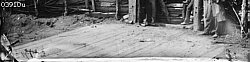
II. Redan with Battery at the Salient (B)
Infantry Parapet of the Right Face
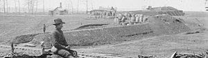 Next in line on the north side of
the Orange and Alexandria Railroad was a redan that combined parapets designed
for a musket armament on the faces with a curved embrasured battery for three
guns at the salient. Structural features of this work's infantry profile
can be fairly well described since the end of the parapet is clearly visible
next to the railroad tracks. This is a breastwork parapet without a raised
banquette or banquette slope, but with other features common to this type
of parapet well defined. The line of the interior crest can be traced from
the end of the infantry parapet to the raised parapet of the salient battery
by following the succession of revetment posts. The nature of the revetment
is suggested by the horizontal timbers held in place by slightly sloped posts
that are visible at the extremity of the parapet next the tracks. The superior
slope seems to be about 3 feet thick at the top and rather flat without a
distinct plongee. Next in line on the north side of
the Orange and Alexandria Railroad was a redan that combined parapets designed
for a musket armament on the faces with a curved embrasured battery for three
guns at the salient. Structural features of this work's infantry profile
can be fairly well described since the end of the parapet is clearly visible
next to the railroad tracks. This is a breastwork parapet without a raised
banquette or banquette slope, but with other features common to this type
of parapet well defined. The line of the interior crest can be traced from
the end of the infantry parapet to the raised parapet of the salient battery
by following the succession of revetment posts. The nature of the revetment
is suggested by the horizontal timbers held in place by slightly sloped posts
that are visible at the extremity of the parapet next the tracks. The superior
slope seems to be about 3 feet thick at the top and rather flat without a
distinct plongee.
 The line of the exterior crest is very distinct
and shows that the parapet had a very equal thickness throughout its length.
The exterior slope falls at what appears to be about a 45 degree angle toward
the ditch without intervention of a berm. Lines and slopes of the ditch are
rather indistinct; width at the top was about 12 to 16 feet, but the maximum
depth was probably only 3 to 4 and one-half feet. Still, the height of the
parapet combined with the ditch would have made this a significant obstacle
for assaulting troops to climb over under fire. One section of the exterior
slope seems to be sliding into the ditch while another section, immediately
adjoining the raised parapet of the battery, shows the The line of the exterior crest is very distinct
and shows that the parapet had a very equal thickness throughout its length.
The exterior slope falls at what appears to be about a 45 degree angle toward
the ditch without intervention of a berm. Lines and slopes of the ditch are
rather indistinct; width at the top was about 12 to 16 feet, but the maximum
depth was probably only 3 to 4 and one-half feet. Still, the height of the
parapet combined with the ditch would have made this a significant obstacle
for assaulting troops to climb over under fire. One section of the exterior
slope seems to be sliding into the ditch while another section, immediately
adjoining the raised parapet of the battery, shows the
 distinct line of the natural level of the ground.
One unusual feature exhibited by the profile of this parapet is the presence
of a slight epaulment immediately in rear of the banquette that runs nearly
the full length of the parapet to the salient battery. This feature seems
a bit too low to provide effective protection from bursting shells or reverse
fire; it would certainly be an obstacle to reserves advancing to support
troops manning the parapet. One has to wonder whether this might have been
intended as a psychological barrier intended to help keep untested troops
under fire for the first time at their posts on the parapet. distinct line of the natural level of the ground.
One unusual feature exhibited by the profile of this parapet is the presence
of a slight epaulment immediately in rear of the banquette that runs nearly
the full length of the parapet to the salient battery. This feature seems
a bit too low to provide effective protection from bursting shells or reverse
fire; it would certainly be an obstacle to reserves advancing to support
troops manning the parapet. One has to wonder whether this might have been
intended as a psychological barrier intended to help keep untested troops
under fire for the first time at their posts on the parapet.
Salient Battery
 The distinct lines of the infantry
parapet terminate rather abruptly as they intersect the lines of raised parapet
of the salient battery. The interior crest of the battery parapet was about
2/3 higher than the adjoining infantry parapet and at least twice as thick
at the top; the exterior slope falls at about a 45 degree angle onto a narrow
berm. Although the ditch in front of the battery parapet can be seen clearly,
it seems to have combined a rather sharply angled scarp with a gently sloped
counterscarp. It would probably have been fairly easy for an assaulting body
of troops to enter the ditch in front of the salient battery, but it would
have been quite difficult for attacking troops to climb the scarp and scale
the parapet. The distinct lines of the infantry
parapet terminate rather abruptly as they intersect the lines of raised parapet
of the salient battery. The interior crest of the battery parapet was about
2/3 higher than the adjoining infantry parapet and at least twice as thick
at the top; the exterior slope falls at about a 45 degree angle onto a narrow
berm. Although the ditch in front of the battery parapet can be seen clearly,
it seems to have combined a rather sharply angled scarp with a gently sloped
counterscarp. It would probably have been fairly easy for an assaulting body
of troops to enter the ditch in front of the salient battery, but it would
have been quite difficult for attacking troops to climb the scarp and scale
the parapet.
As to the structural details of this battery, it appears to be
constructed in much the same fashion as the battery south of the railroad.
The tops of a series of posts can be seen rising above the interior crest
and some branches can be seen jutting out from the slope connecting to the
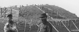
infantry parapet. Another photograph (03442u) taken from the interior of
this battery shows that it too combined a low post and timber revetment with
hurdle work and was arranged with tackle posts for maneuvering naval ordnance
on ship's trucks.
That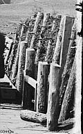 photograph also shows the ends of branches
sticking out from the revetment that have been buried in the body of parapet
to bind the rocky soil into a single mass. photograph also shows the ends of branches
sticking out from the revetment that have been buried in the body of parapet
to bind the rocky soil into a single mass.
Photograph 03442 shows some of the battery's interior details
that can not seen in the photograph under current consideration. This photograph
confirms that the raised battery parapet had a split revetment that was in
much better condition when the photograph was made than that of the battery
south of the railroad. Many small cut branches can be sticking out of the
rough hurdlework revetment, again confirming that the earth parapet was
stabilized by inclusion of leafy branches buried in the body of the parapet
near the interior slope. Again, tackle posts are present showing that this
battery was also designed for an armament of heavy naval ordnance mounted
on ship's trucks. A heurter was noticed at the foot of the interior slope
of the battery south of the railroad; the embrasure shown in this photograph
had a stopping beam suspended between two short posts inside the tackle posts
nearest the mouth of the embrasure. This beam would catch a truck on its
forward cheeks and prevent it from running into the interior slope.
Some construction details of the gun platform are visible in this
photograph (03442u). The platform is rectangular with 15 uniformly sized
deck planks laid with their length perpendicular to the direction of the
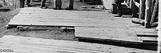 embrasure mouth. Planks were laid on a foundation
consisting of hewn timber sleepers covered with a crossing layer of thin
planks. This platform was sloped upward toward the rear, a common feature
designed to assist in shortening the recoil distance of the piece when discharged
and to promote good drainage. A small rectangular addition to the platform
can be seen in the lower right foreground of the photograph. This addition
seems to have two planks affixed to it that run perpendicular to the direction
of the interior slope of the parapet; these may have been a rather ad hoc
stand for a pile of ready ammunition. embrasure mouth. Planks were laid on a foundation
consisting of hewn timber sleepers covered with a crossing layer of thin
planks. This platform was sloped upward toward the rear, a common feature
designed to assist in shortening the recoil distance of the piece when discharged
and to promote good drainage. A small rectangular addition to the platform
can be seen in the lower right foreground of the photograph. This addition
seems to have two planks affixed to it that run perpendicular to the direction
of the interior slope of the parapet; these may have been a rather ad hoc
stand for a pile of ready ammunition.
 Ground immediately in rear of the platform
slopes downward at the natural of the soil and falls into a small drainage
trench that runs along the rear of the salient battery. This seems to indicate
that this was probably a cavalier battery raised above the natural level
of the site. It may be assumed that this particular arrangement was designed
specifically for the purpose of providing the structural means to give naval
ordnance its full effect in a foreign environment. Ground immediately in rear of the platform
slopes downward at the natural of the soil and falls into a small drainage
trench that runs along the rear of the salient battery. This seems to indicate
that this was probably a cavalier battery raised above the natural level
of the site. It may be assumed that this particular arrangement was designed
specifically for the purpose of providing the structural means to give naval
ordnance its full effect in a foreign environment.
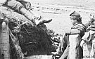
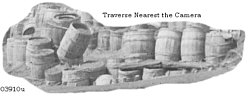
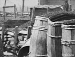
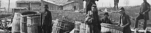
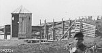
Cask Paradoses
 Two of the more interesting fortification
features visible in the photograph (03910u) are the two cask traverses
immediately to the left (rear) of the salient battery. Although these appear
at first glance to be closely associated with the battery, they were not
integral elements of the battery, but were somewhat behind and to either
side of the raised terre-plein of the battery. Instead, these were bullet-proof
defilade traverses that extended across the terre-parade of the redan and,
as such, can be classified as parados intended to screen the interior of
the work and the rear of the redan faces from the two points of commanding
ground on either flank of the redan; these two points being the battery south
of the railroad and the most northerly redan farthest from the camera. The
second traverse Two of the more interesting fortification
features visible in the photograph (03910u) are the two cask traverses
immediately to the left (rear) of the salient battery. Although these appear
at first glance to be closely associated with the battery, they were not
integral elements of the battery, but were somewhat behind and to either
side of the raised terre-plein of the battery. Instead, these were bullet-proof
defilade traverses that extended across the terre-parade of the redan and,
as such, can be classified as parados intended to screen the interior of
the work and the rear of the redan faces from the two points of commanding
ground on either flank of the redan; these two points being the battery south
of the railroad and the most northerly redan farthest from the camera. The
second traverse
 distant from the camera does, in fact, screen
the interior slope of the opposite face of the redan from the camera's view.
Except, of course, for those points where the casks have been displaced or
were not positioned properly in the first place which allowed the camera
to see the post and timber revetment of the work's interior slope. distant from the camera does, in fact, screen
the interior slope of the opposite face of the redan from the camera's view.
Except, of course, for those points where the casks have been displaced or
were not positioned properly in the first place which allowed the camera
to see the post and timber revetment of the work's interior slope.
Structurally, these traverses were laid out in much the same fashion
as gabion traverses with the exception that the lower tier of the traverses
was only two casks wide and the upper tier only one cask wide. It seems doubtful
whether these traverses had the mass necessary to withstand any fire larger
than that of a common
 musket. Certainly the method of construction
did not promote stability of the traverse. The casks of the lower tier have
been laid side to side in two rows; in the far traverse earth was excavated
from a wide, but shallow, trench and used to fill each cask and heap the
soil on top of them to form a bed for the upper tier which was also filled
with earth. Construction of the near traverse did not reach this point: the
casks have been filled, but large gaps between the casks are visible, indicating
that the voids between the casks were not filled. This would have been positively
necessary to convert the bottom row from a series of independent elements
into a unified mass. musket. Certainly the method of construction
did not promote stability of the traverse. The casks of the lower tier have
been laid side to side in two rows; in the far traverse earth was excavated
from a wide, but shallow, trench and used to fill each cask and heap the
soil on top of them to form a bed for the upper tier which was also filled
with earth. Construction of the near traverse did not reach this point: the
casks have been filled, but large gaps between the casks are visible, indicating
that the voids between the casks were not filled. This would have been positively
necessary to convert the bottom row from a series of independent elements
into a unified mass.
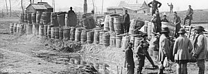
Upper tier casks seem to have been laid either along the center
line of the two rows of the lower tier or directly on top casks of the lower
tier, but, judging from the number of upper tier casks that have been displaced
or knocked completely off the traverses, they were not anchored into place.
Upper tier casks revet and bond the traverse in the same way that a glass
holds water, that is, not at all. Solid shot striking a cask of the upper
tier would probably shatter the cask staves (sending wood splinters flying
in all directions) and knock the cask completely out of place. In short,
these interesting features reveal the hope and inexperience of their designer,
but would not have been particularly useful for the defense of this field
work. Once one of the casks had been shot away, it seems probable that troops
manning the parapet in front of it would lose a bit of their confidence in
the protective value of this field work.
Turning again to the closer view of this redan provided by the
second photograph (03442u) some sections of the revetment of the work's left
(north) face parapet can be seen through breaks in the cask traverse. This
line of parapet had a post and split timber revetment. Posts are set at an
appropriate angle to give the interior its necessary slope, but the split
timbers give the revetment a rather discordant and ad hoc appearance; the
 horizontal timbers seem to have been split in
a rather hap-hazard fashion and were not given uniform widths or lengths.
Some attempt seems to have been made to anchor the posts to the body of the
parapet using cut "V" shaped branches. These anchoring branches were positioned
about 1 to 1 1/2 feet above the foot of the interior slope, this would have
been was too low to influence the stability of the upper reaches of the posts.
This may be taken as another indication of the inexperience of the engineer
or other officer assigned to direct the actual construction of the work. horizontal timbers seem to have been split in
a rather hap-hazard fashion and were not given uniform widths or lengths.
Some attempt seems to have been made to anchor the posts to the body of the
parapet using cut "V" shaped branches. These anchoring branches were positioned
about 1 to 1 1/2 feet above the foot of the interior slope, this would have
been was too low to influence the stability of the upper reaches of the posts.
This may be taken as another indication of the inexperience of the engineer
or other officer assigned to direct the actual construction of the work.
 This close view also confirms that
there was a distinct separation between this redan and the next battery (C)
to the north. Looking through breaks in the cask traverse the sloping extremity
of the next battery can clearly be seen over the top of the redan's left
face parapet revetment. The parapet of the next battery can be seen rising
to a level and maintaining that level up to the nearest embrasure of the
battery. The heads of this work's revetment posts form a distinct and even
line that marks the work's interior crest. Both of this work's two embrasures
are also visible; their cheeks were given a post and horizontal timber revetment.
Horizontal timbers were cut to follow the profile of the parapet's exterior
slope. Since the interior of the battery can not be seen, it can not be
determined whether these embrasures were arranged for heavy naval ordnance
maneuvered with tackle, but the probability is that it This close view also confirms that
there was a distinct separation between this redan and the next battery (C)
to the north. Looking through breaks in the cask traverse the sloping extremity
of the next battery can clearly be seen over the top of the redan's left
face parapet revetment. The parapet of the next battery can be seen rising
to a level and maintaining that level up to the nearest embrasure of the
battery. The heads of this work's revetment posts form a distinct and even
line that marks the work's interior crest. Both of this work's two embrasures
are also visible; their cheeks were given a post and horizontal timber revetment.
Horizontal timbers were cut to follow the profile of the parapet's exterior
slope. Since the interior of the battery can not be seen, it can not be
determined whether these embrasures were arranged for heavy naval ordnance
maneuvered with tackle, but the probability is that it
 was. Unlike the redans to its right (south) and
left (north) this battery's interior crest was not raised higher than that
of the adjoining line of parapet. This was probably due to the fact that
this was a small work intended strictly as cover for its artillery armament
and did not include any substantial length of banquette for a musket armament. was. Unlike the redans to its right (south) and
left (north) this battery's interior crest was not raised higher than that
of the adjoining line of parapet. This was probably due to the fact that
this was a small work intended strictly as cover for its artillery armament
and did not include any substantial length of banquette for a musket armament.
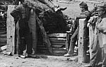
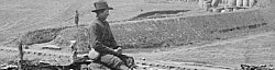
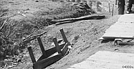
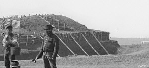
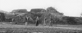
III. Northeast Redan (D)
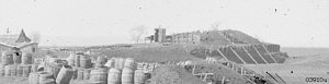 The field work at the northeast angle
of the interior line of works (marked D on the map) exhibits a number of
peculiarities that demand attention. Its trace was very similar to the first
work north of the railroad: it was a redan with two distinct faces that included
a curvilinear raised battery at the salient angle. The parapet of the right
(south) face can be seen above the barrel traverse of the first redan north
of the railroad (B); it appears to be a rather normal parapet prepared for
a musket armament. This line of parapet joins the raised mound of the salient
battery at the point where an exterior revetment sustaining the lower portions
of the battery's exterior slope at a vertical begins. This revetment, which
is supported by 5 long timber shores, follows the outline of the battery.
As with the previous redan, the parapet of the battery is raised well above
the height of the infantry parapet forming the redan's near face. A single
embrasure can clearly be seen in battery parapet with its cheeks sustained
by a post and timber revetment. A tall post and timber revetment seems to
cover the rear of the salient battery. Another line of revetment can be followed
from the salient battery toward the left where it become very indistinct
and mixes with the background. The field work at the northeast angle
of the interior line of works (marked D on the map) exhibits a number of
peculiarities that demand attention. Its trace was very similar to the first
work north of the railroad: it was a redan with two distinct faces that included
a curvilinear raised battery at the salient angle. The parapet of the right
(south) face can be seen above the barrel traverse of the first redan north
of the railroad (B); it appears to be a rather normal parapet prepared for
a musket armament. This line of parapet joins the raised mound of the salient
battery at the point where an exterior revetment sustaining the lower portions
of the battery's exterior slope at a vertical begins. This revetment, which
is supported by 5 long timber shores, follows the outline of the battery.
As with the previous redan, the parapet of the battery is raised well above
the height of the infantry parapet forming the redan's near face. A single
embrasure can clearly be seen in battery parapet with its cheeks sustained
by a post and timber revetment. A tall post and timber revetment seems to
cover the rear of the salient battery. Another line of revetment can be followed
from the salient battery toward the left where it become very indistinct
and mixes with the background.
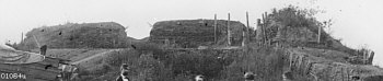
 To examine this work in a bit more
detail it will be necessary to call the closer view offered by the second
photograph (03442u) into service. This photograph shows that the redan was
covered by a continuous ditch that appears to have had somewhat greater
dimensions than the ditches in front of the other redan to the south (B).
The exterior slope of the infantry parapet falls onto a very slight berm,
no more than a few inches wide, just above the crest of the scarp. But this
berm widens out below the exterior slope revetment of the salient battery
parapet and takes on a slope of varying degrees until it reaches within a
few yards of the point where the parapet's curve takes it out of the camera's
view where this berm becomes quite flat. The infantry parapet was To examine this work in a bit more
detail it will be necessary to call the closer view offered by the second
photograph (03442u) into service. This photograph shows that the redan was
covered by a continuous ditch that appears to have had somewhat greater
dimensions than the ditches in front of the other redan to the south (B).
The exterior slope of the infantry parapet falls onto a very slight berm,
no more than a few inches wide, just above the crest of the scarp. But this
berm widens out below the exterior slope revetment of the salient battery
parapet and takes on a slope of varying degrees until it reaches within a
few yards of the point where the parapet's curve takes it out of the camera's
view where this berm becomes quite flat. The infantry parapet was
 not on a level, but rises gently from its extremity
(to the left, above the small two gun battery (C)) to the point where it
joins the raised salient battery. It is possible to make out the tops of
a few of the parapet's revetment posts that mark the line of the interior
crest. The two dimensional nature of the camera's point of view does not
allow a very good impression of the exterior lines of the parapet; the superior
slope seems to fall onto the exterior slope without assistance of a strong
line of demarcation. not on a level, but rises gently from its extremity
(to the left, above the small two gun battery (C)) to the point where it
joins the raised salient battery. It is possible to make out the tops of
a few of the parapet's revetment posts that mark the line of the interior
crest. The two dimensional nature of the camera's point of view does not
allow a very good impression of the exterior lines of the parapet; the superior
slope seems to fall onto the exterior slope without assistance of a strong
line of demarcation.
 The transitional area where the infantry
parapet joins the raised parapet of the salient battery is influenced by
the presence of the exterior revetment of the battery's exterior slope, which
deforms the last few feet of the infantry parapet's exterior slope. The gentleman
holding the water bucket unfortunately blocked the camera's view of the actual
transition between the unrevetted and revetted exterior slopes. Above this,
the transition between the infantry parapet's superior slope and raised battery
parapet is quite abrupt with the end of the battery parapet almost double
the height of the infantry parapet and sustained by a post and timber revetment.
This revetment appears to have a vertical angle and seems to be much too
rectangular to represent the actual profile of the battery parapet; the exterior
end of the revetment actually casts a shadow onto the upper portion of the
exterior slope next to it. The transitional area where the infantry
parapet joins the raised parapet of the salient battery is influenced by
the presence of the exterior revetment of the battery's exterior slope, which
deforms the last few feet of the infantry parapet's exterior slope. The gentleman
holding the water bucket unfortunately blocked the camera's view of the actual
transition between the unrevetted and revetted exterior slopes. Above this,
the transition between the infantry parapet's superior slope and raised battery
parapet is quite abrupt with the end of the battery parapet almost double
the height of the infantry parapet and sustained by a post and timber revetment.
This revetment appears to have a vertical angle and seems to be much too
rectangular to represent the actual profile of the battery parapet; the exterior
end of the revetment actually casts a shadow onto the upper portion of the
exterior slope next to it.
From this end revetment the battery parapet rises in height as
it approaches the revetment of the embrasure, it seems to take a definite
level and keep it beyond the embrasure. The embrasure itself is really quite
interesting;
 the revetment does follow the parapet profile
fairly closely, even if the parapet appears to follow a consistent slope
from the interior crest without any strong lines separating the superior
from the exterior slope. Enough of the interior of the embrasure is visible
to determine that the sole was appropriately sloped downward from the mouth
on the interior slope of the parapet to its defining exterior line along
the top of the exterior slope's revetment. the revetment does follow the parapet profile
fairly closely, even if the parapet appears to follow a consistent slope
from the interior crest without any strong lines separating the superior
from the exterior slope. Enough of the interior of the embrasure is visible
to determine that the sole was appropriately sloped downward from the mouth
on the interior slope of the parapet to its defining exterior line along
the top of the exterior slope's revetment.
Wood exposed to artillery fire was not generally not considered
a good thing, it therefore seems a bit odd that this field work would include
a very substantial post and timber revetment along the lower portion of its
exterior slope. This revetment would have increased the difficulty assaulting
troops would experience getting into the work over the battery parapet,
especially when subject to flanking fire provided by the collateral two gun
battery (C); but the far side of the parapet that can not be seen by the
camera was not as well flanked. The revetment combined with the berm that
lead to the joint between the raised battery parapet and lower infantry parapet
would have provided a covered passageway for assaulting troops to easily
reach the top of
 the infantry parapet and rear of the battery.
The severe consequences of the this revetment's destruction by distant artillery
prior to an assault can well be imagined, that is, the parapet would probably
slide into the ditch. This would both steal the defenders' cover and provide
assaulting troops with a ramp across the work's ditch. It seems doubtful
that any competent engineer would design this dangerous feature into a field;
more than likely it was yet another result of inexperience either by way
of an initial error in laying out the lines of the work on the ground or
a mistaken estimate of the soil's native capacity for holding a slope under
pressure of the mass of the parapet. This last point seems to be confirmed
by the apparent sliding and rotation of the revetment posts that was checked
by the addition of the five long timber shores that stretched from the
counterscarp of the ditch to the upper portions of the posts. Given the sharp
slope of the berm at the near end of the revetment it may also be assumed
that the revetment was constructed after the parapet was completed specifically
to prevent the weight of the parapet from crushing the scarp and carrying
the protective covering mass into the ditch. the infantry parapet and rear of the battery.
The severe consequences of the this revetment's destruction by distant artillery
prior to an assault can well be imagined, that is, the parapet would probably
slide into the ditch. This would both steal the defenders' cover and provide
assaulting troops with a ramp across the work's ditch. It seems doubtful
that any competent engineer would design this dangerous feature into a field;
more than likely it was yet another result of inexperience either by way
of an initial error in laying out the lines of the work on the ground or
a mistaken estimate of the soil's native capacity for holding a slope under
pressure of the mass of the parapet. This last point seems to be confirmed
by the apparent sliding and rotation of the revetment posts that was checked
by the addition of the five long timber shores that stretched from the
counterscarp of the ditch to the upper portions of the posts. Given the sharp
slope of the berm at the near end of the revetment it may also be assumed
that the revetment was constructed after the parapet was completed specifically
to prevent the weight of the parapet from crushing the scarp and carrying
the protective covering mass into the ditch.
The crest of the scarp can be seen in silhouette where the battery's
curve turns it out of the camera's view. It is notable that the scarp appears
to have an almost vertical angle at the top before taking a sharp slope down
to the bottom of the ditch. This tends to confirm that the scarp was not
given an angle sufficient to sustain the weight of the parapet. The bottom
of the ditch appears to vary in depth from 6 to 8 or more feet, but it also
seems to lack a distinct counterscarp in the section visible in the photograph.
In fact, ground around the work
 seems to roll gently into the ditch until it
meets the foot of the scarp where it takes on a very sharp angle. This would
have made it fairly easy for assaulting troops to reach the foot of the scarp,
but once there, assuming that the exterior slope revetment was still intact,
they would encounter a very serious series of obstacles. They would be compelled
to scale the scarp to mount the berm, then climb up the revetment to get
onto the upper reaches of the exterior slope, and only then could they try
to go over the superior slope or enter the work through the embrasures. All
of this while under a flanking and reverse fire from the other works composing
the east front of defense. But as has already been pointed out, there would
be no reason to go over the battery parapet when an easier route around it
had been built into the work. seems to roll gently into the ditch until it
meets the foot of the scarp where it takes on a very sharp angle. This would
have made it fairly easy for assaulting troops to reach the foot of the scarp,
but once there, assuming that the exterior slope revetment was still intact,
they would encounter a very serious series of obstacles. They would be compelled
to scale the scarp to mount the berm, then climb up the revetment to get
onto the upper reaches of the exterior slope, and only then could they try
to go over the superior slope or enter the work through the embrasures. All
of this while under a flanking and reverse fire from the other works composing
the east front of defense. But as has already been pointed out, there would
be no reason to go over the battery parapet when an easier route around it
had been built into the work.
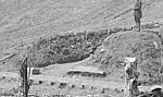
 Unlike the interior slope of the two works
previously discussed, this battery did not have a split revetment; judging
from the portion of the interior slope visible to the camera, this work had
a complete post and timber revetment. This revetment had about 13 horizontal
timber laid one on top of the other that were retained in place by 7 rather
tall posts. At least one of the revetment posts had to be sustained by a
timber shore. The terre-plain of the raised battery was accessed by a ramp,
which can be seen just in front of the sentry box and table. This ramp, along
with other details of the interior of this battery can be seen in yet Unlike the interior slope of the two works
previously discussed, this battery did not have a split revetment; judging
from the portion of the interior slope visible to the camera, this work had
a complete post and timber revetment. This revetment had about 13 horizontal
timber laid one on top of the other that were retained in place by 7 rather
tall posts. At least one of the revetment posts had to be sustained by a
timber shore. The terre-plain of the raised battery was accessed by a ramp,
which can be seen just in front of the sentry box and table. This ramp, along
with other details of the interior of this battery can be seen in yet
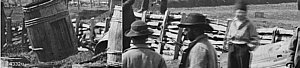
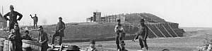
 another photograph (01084u) made in July, 1862
after the series work of deterioration and destruction by scavenging had
been well underway for quite some time. another photograph (01084u) made in July, 1862
after the series work of deterioration and destruction by scavenging had
been well underway for quite some time.
This photograph show the rear of the redan's right face infantry
parapet and the interior of the raised battery. The battery terre-plein was
raised to the level of the superior slope of the infantry parapet; two of
the three embrasures can be seen, the third being hidden by the camera's
angle of view. As with the other batteries, this one includes tackle posts
for maneuvering naval ordnance mounted on ship's trucks. Many small branches
and twigs can be seen sticking out of the interior slope of the battery
 parapet, indicating that this parapet was also constructed
by combining the earth with small branches. The effectiveness of this combination
is obvious since the interior slopes retain almost vertical angles even though
the post and timber revetment has disappeared. Looking toward the exterior
slope of the parapet, the revetment is still present, but the shores seem
to be gone, leaving the revetment posts to continue the process of destruction
by vertical rotation. parapet, indicating that this parapet was also constructed
by combining the earth with small branches. The effectiveness of this combination
is obvious since the interior slopes retain almost vertical angles even though
the post and timber revetment has disappeared. Looking toward the exterior
slope of the parapet, the revetment is still present, but the shores seem
to be gone, leaving the revetment posts to continue the process of destruction
by vertical rotation. |


