Drawing was an important element in the education of engineering
students in the nineteenth century. Fortification drawing prepared students
to formulate ideas and give those ideas concrete expression on paper in a
precise and easily grasped manner. In being able to give an idea precise
expression also had the desirable effect of reinforcing the various principles
of fortification and establishing effective defensive relationships among
the various elements of fortifications. The imposition of the orderly process
required to perform an acceptable drawing tended to prepare students to approach
the design and construction of fortifications and other public works in an
orderly and practical manner.
In point of method and procedure drawing fortifications was not
in any way dissimilar to industrial or mechanical drawing. Basic tools for
performing a drawing were the same: compasses (or dividers) were used for
taking lengths and marking arcs of circles, straightedge rulers for producing
right lines, and a protractor for taking the measure of angles. Other tools
such as curved rulers, triangles, and squares could also be employed to increase
the accuracy and precision of a drawing. Unlike simple geometric constructions,
fortification and other mechanical drawings required the use of proportional
scales (scale of equal parts and diagonal scale of equal parts) to impart
a clear sense of the dimensions and shape of an object represented by a drawing.
A primary object of fortification drawing was to represent the
plan and profile of any particular fortification with sufficient clarity
that any experienced tradesman, mechanic, or military officer could almost
intuitively grasp its shape and dimensions after a few moments' glance without
undue effort or confusion. To accomplish this most fortification drawings
utilized projections of the bounding lines of the elements of a fortification
onto a horizontal plane to provide a plan view of the fortification and profiles
or cross-sections of a fortification projected onto a vertical plane. Multi-plane
drawings were generally only employed to show detailed features within a
fortification (particularly mechanical elements such as drawbridge mechanisms
or unique and uncommon secondary structures) and, occasionally, to provide
perspective views as guides to explain the general appearance of a fortification.
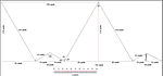
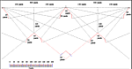
Ten exercises in drawing the outlines of lines of field works
have been provided below as a means of gaining some familiarity with a simplified
adaptation of the orderly procedure required to perform fortification drawings.
Each exercise projects the line of the interior crest of a parapet onto a
horizontal plane to produce a plan view of the lines of the interior crest.
This simplified view that excludes all other features of the parapet and
interior arrangements of the fortification tends to give greater clarity
to the defensive characteristics inherent to each trace, that is, how one
section of a line might defend another with its fire and how thoroughly ground
immediately in front of a line was defended by crossing columns of fire.
Each exercise may be performed using compass, ruled straightedge, protractor,
pencil applied to a large sheet of paper well fixed to a stable flat surface.
|